The SMD-Breadboard and Breakout-Boards are now available at Segor!
Introduction
Probably everyone in the field of electronics development has had to do with breadboards and perfboards. The most astonishing and complicated circuits have been implemented on those, at Konstruktiv as well.
Nowadays we consider the handling of parts for push-through assembly no longer as up-to-date. They are also quite prone to errors. So Tristan August had an idea (again): a breadboard for SMD components! With a signal bus! On which you can easily solder SMD capacitors! With LEDs! Thought and done.
Features
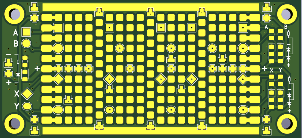
In general, the SMD breadboard consists of pads that are ideally spaced to be equipped with 0805 components. Components with 1206 or 0603 footprints will also fit. The pads on the right and left edge are slightly larger to make it easier to solder cables from the outside. Additional connected power and bus pads are attached to the front and back.
Power-Pads
On the SMD breadboard, pads are distributed in places considered sensible to us, which can be connected to a supply voltage and ground. In addition, there is a longer open ground plane at the top and bottom so that connections can be made quickly and easily.
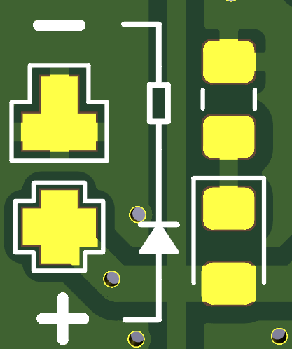
At the four corners, Power and Ground pads have been placed together so that SMD capacitors can easily be soldered to stabilize the supply voltage.
On the left side there is a place for an LED with a series resistor. Place those to see if the power supply is on.
Power pads can be found on both the front and the back of the board.
Offset-Pads
On the board there are three rows offset from the others. These rows are particularly suitable for soldering SOT-23 or SOT-323 components such as transistors and the like. There are bus pads nearby that can be connected to it.
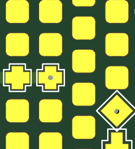
BUS-Pads
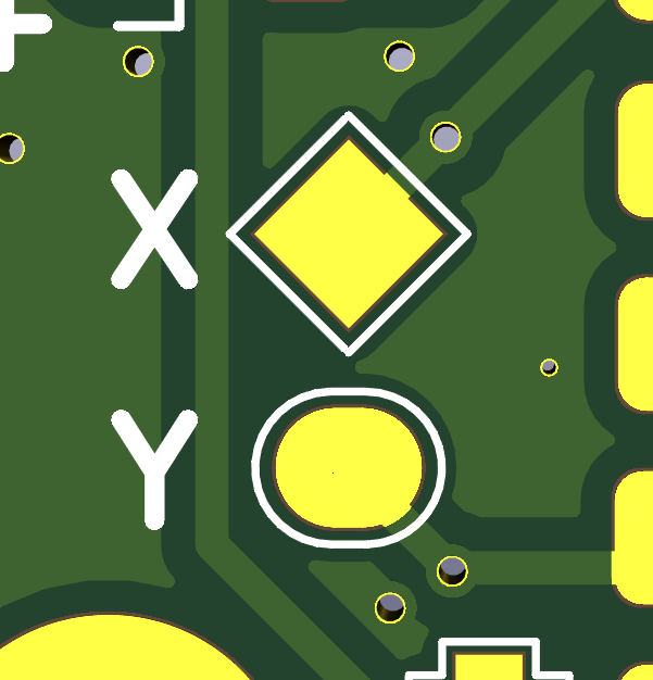
In addition to the power pads, the SMD breadboard has four buses, marked with A, B, X and Y. They can be used to distribute signals across the board. Pads that are connected to a bus have a special shape so that they can be told apart from “normal” pads. The correspondingly shaped pads are each connected to one another.
BUS-LEDs
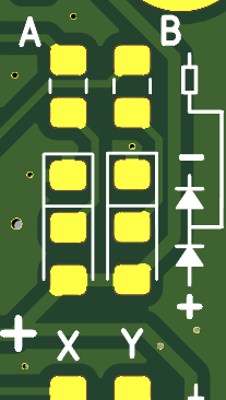
On the right side of the board there are places for LEDs and series resistors that are connected to the buses. The LEDs can be placed so that they are pulled to Ground or connected to Power.
Cut away BUS-Pads

If it turns out during soldering that individual pads should not be connected to the bus after all, they can be separated by simply scratching through a thin track on the back.
IC Breakout Boards
In order to be able to work with more complex components on the SMD breadboard, we have designed a number of breakout boards to match our grid.
Currently are available:
-
– SOT236
– SO8, SO8W
– SO14/16, W
– QFN-16
The breakout boards have castellated holes on the edges so that they can be soldered directly onto the breadboard.
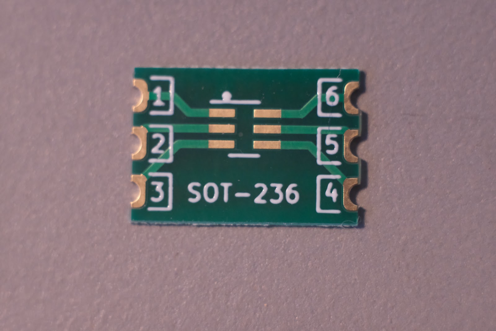
SOT-236 Breakout Board
SO-8 Breakout Board
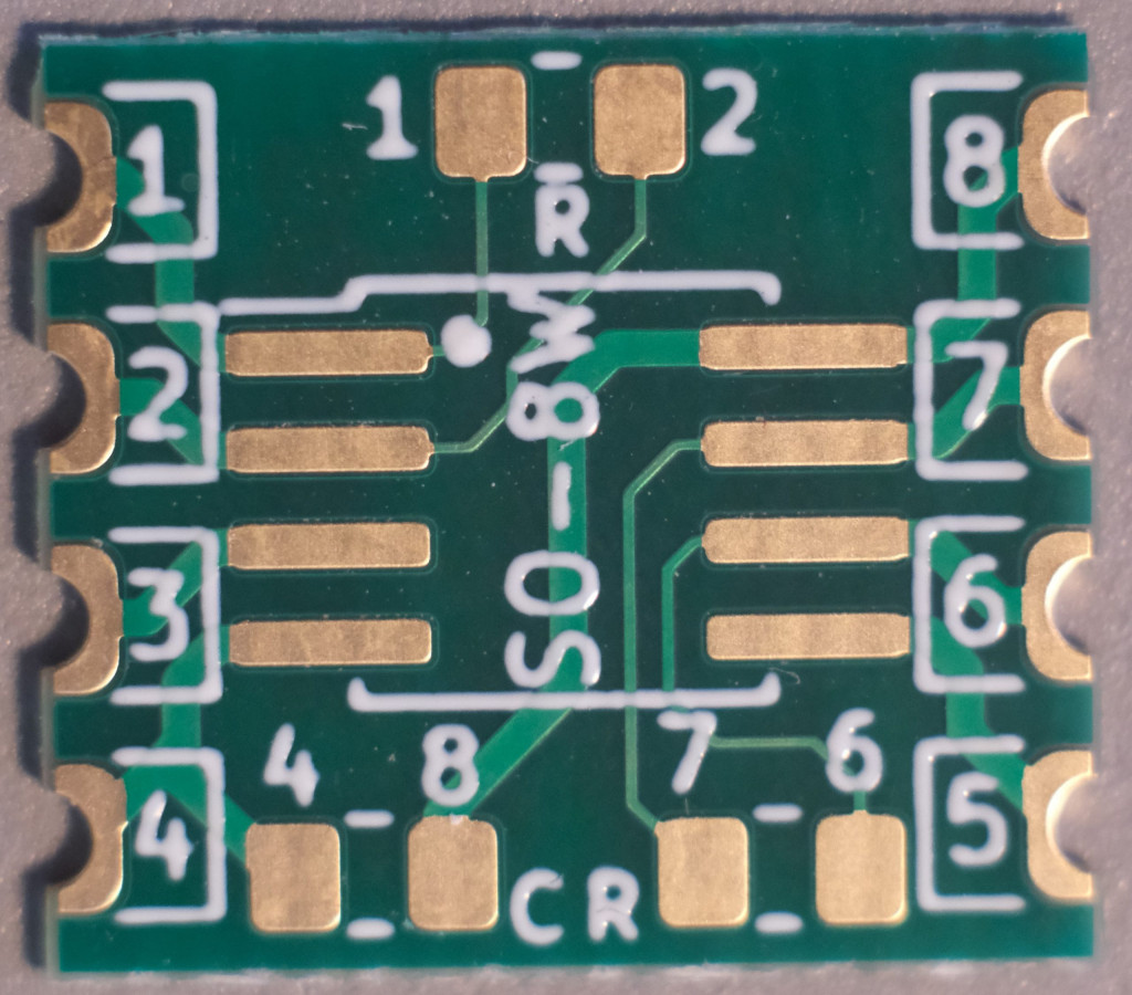
SO-8 breakout board 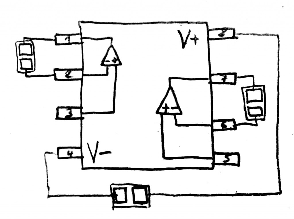
Since there are many operational amplifiers in SO8 housings, some components have been specially designed for this that are frequently used:
- decoupling capacitor between pin 4 and 8
- Capacitor or resistor in the feedback loop between pins 1 and 2 or 6 and 7
SO-14/16 Breakout Board
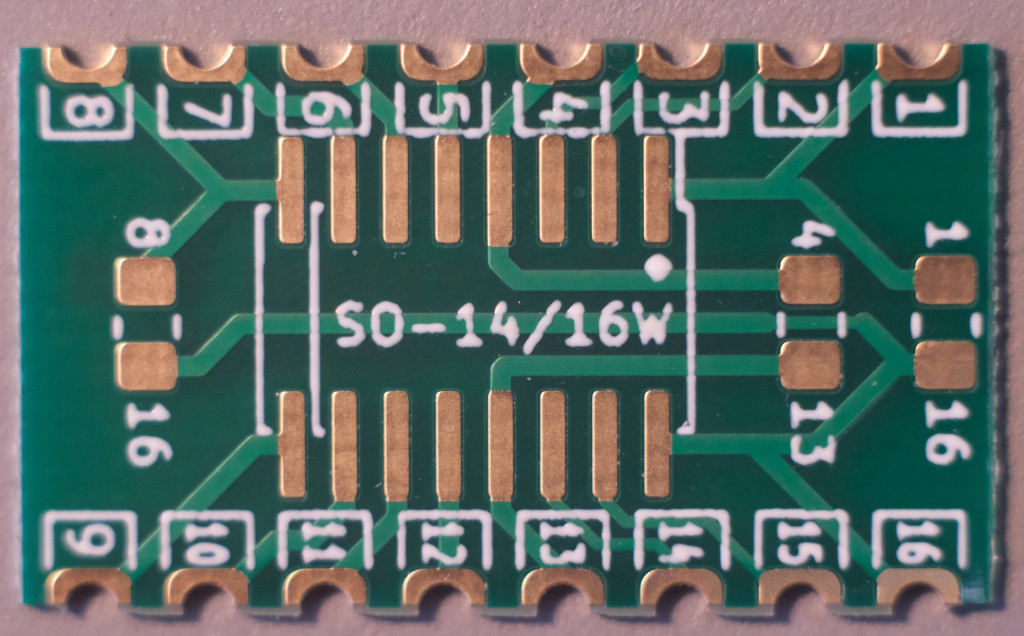
The breakout board can be used for SO-14 and SO-16 components. Depending on the application, a decoupling capacitor can be soldered directly onto the breakout board
- between PIN 1 and 16 on many micro-controllers, e.g. ATtiny
- between pin 4 and 13 on many operational amplifiers
- Between pin 8 and 16 on many CMOS ICs
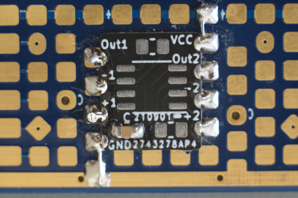
QFN-16 Breakout Board
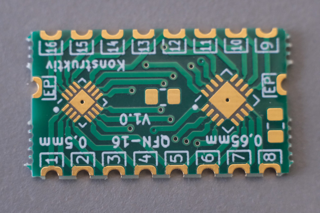
The QFN-16 Breakout Board can be used for both QFN-16s with a pitch of 0.5mm and 0.65mm; the two footprints are parallel on a breakout board.
Suppliers
SMD-Breadboard and various Breakout-Boards can be ordered at SEGOR-electronics (www.segor.de).
Downloads
Version History
V1.1 TZ Edition
V1.2 Segor Edition, Konstruktiv Christmas Edition
Change Log
V1.2 Re-Design
Known Issues
V1.2: The plus pad on the right side of the back is not connected
Feedback and ideas
We look forward to your feedback and further ideas! Please write to us! smd-breadboard@konstruktiv-berlin.de